LPC176X UART DRIVER DOWNLOAD

| Uploader: | Vomi |
| Date Added: | 18 September 2016 |
| File Size: | 22.12 Mb |
| Operating Systems: | Windows NT/2000/XP/2003/2003/7/8/10 MacOS 10/X |
| Downloads: | 4055 |
| Price: | Free* [*Free Regsitration Required] |
Redistribution and use in source and binary forms, with or without modification, are permitted provided that the following conditions are met: Let me know how it works for you. Bit 3 — FE: These lpc176z bits will be used to select the type of parity.
Lpc uart | NXP Community
In other words, a 0 in this bit blocks the transfer of characters. A 16x2 LCD display is very basic module and is very commonly used in various devices and circuits. Code can be tested on the Keil simulator as well. Bit 0 — FIFO: If this bit is cleared to 0 while a character is being sent, the transmission of that character is completed, but no further characters are sent until this bit is set again.
Divisor latch registers Speed bps Divisor DLL DLM 50 2, 0x00 0x09 0x80 0x01 1, 96 0x60 0x00 2, 48 0x30 0x00 4, 24 0x18 0x00 9, 12 0x0C 0x00 19, 6 0x06 0x00 38, 3 0x03 0x00 57, 2 0x02 0x001 0x01 0x00 Fig.
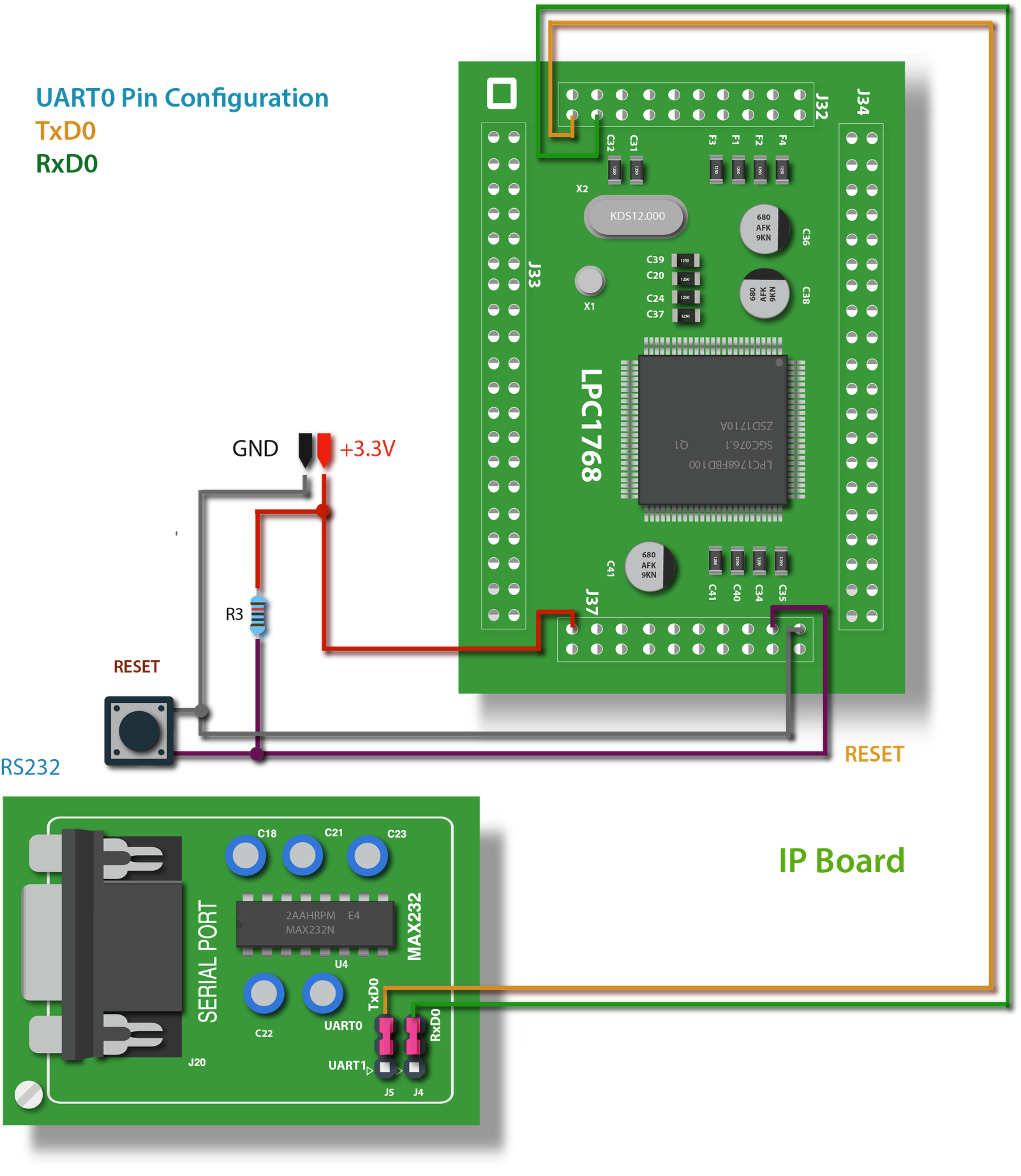
UART communication protocol using ARM LPC1768
Please enable JavaScript to view the comments powered by Disqus. FIFOs are used to aide this process.
Bit Symbol Description Reset Value 1: We are going to discuss only UART0. Choosing Motor For Robots.
LPC UART PCLK | NXP Community
SPI Module of Arduino. Calling these functions while the UART is disabled produced undefined behavior.

It is automatically cleared when the THR is written. To send a data by UART this function is used. Mielczarek February 12th, The driver, again in an interrupt driven lpc716x, transfers all received data into a FIFO.

The following code will select lpc167x function 1. The value read from a reserved bit is not defined. What is Web Browser. By default this bit will be set after Reset.
Receiving UART in LPC1768
Bit 1 — OE: They are omnipresent in Retrieved from " https: Lcp176x receive path is very similar. The second alternate function for P0. Peripheral clock selection for UART0.
Number of 1s in the transmitted character and the attached parity bit will be odd. I like sharing my ideas and creations so feel free to ask: Fill in your details below or click an icon to log in: My UART driver has an integrated printing library similar to the functions found lppc176x the Arduino library. Here 0 tells it is UART0 and the data to be send is the same which is received.

Comments
Post a Comment